Garrattfan's Modelrailroading Pages

NS class 5000
Assembling the motion gear
- Introduction
- War locomotives in general
- History of the 5000 Class
- Inventory of the kit
- Instruction manual
- Chassis jig
- Chassis preparation
- Drive train preparation
- Chassis assembly
- Drive train assembly
- Chassis completion
- Motion gear
- Tender construction
- Superstructure locomotive
- Detailing locomotive
- Completed loco before painting
- Painting
- Final assembly
- Completed loco

In het Nederlands
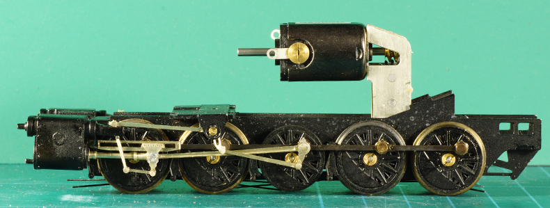
A quick preview of the end result of this page. IntroductionWith a running chassis and the coupling rods temporarily in place it is time to complete the motion gear.
Note: If you are reading this page separately from the NS 5000 project it is a good thing to realise that in most kits you are now reaching a point of no return as it comes to painting the chassis. So in general it is a good thing to have the chassis painted before assembling the motion gear. Admittedly you will have to worry about avoiding damage to the paint while working on the motion gear, but at the same you are saving great time on painting the chassis after the assembly of the motion gear. It is a choice between two setbacks.
How important is a good valve gear? Well, suppose your locomotive's valve gear has a success rate of 99,5% for each of the 28 (!) potential fail spots in the motion gear. Looks good, but the accumulated success rate will be 0,8691 or a meagre 87 %, telling you it will hamper or even stall every tenth revolution. So when you build your valve gear accept nothing less than perfection!! You can beat the maths above with logic, accuracy and a bit of perseverance.
For the sake of that perfection I do not rivet my motion gear but I use a rather counterintuitive method for this: soldering. Keep breathing, do not call 911. Just keep reading. I have described this method on three separate pages while building the NGG16 and AD60 valve gear. I will know narrate the whole story into one page for future reference. |
|
Why solder? |
|
| The classic way of assembling valve gear is riveting. Mass producers often do it, so it seems the logical way to go. Really? Take a look at the photos below. | |
A mass produced motion gear from Roco's BR93 shows how sloppy riveted gear can be, the rods are dangling all over the place. |
The huge space a truly riveted rivet takes. Note the huge play between the crank rod (bottom) and the return crank (top). Also note the flange at the back of the return crank which necessitates an unprototypical joggle in the return crank to prevent the back of the rivet catching on the passing drive rod. |
After some attempts on riveting and being decidedly unhappy about its unpredictability I decided to have a go at soldering. With considerable more success, if I may say so myself. Modellers seem to shy away from soldering but without good reason. Soldering the valve gear needs some getting used to, but it has distinct advantages
Of course you may consider riveting, it is after all your model. But if you are building the locomotive kits and you choose to rivet the valve gear because you are afraid of soldering, well frankly you should think again. Soldering is a basic technique any locomotive builder should master. Admittedly soldering the motion gear gear not the thing to start with but hey, at the same time it is no black magic.
I have adapted a method to solder motion gear that is originally described by Iain Rice in his book "Locomotive Kit Chassis Construction". The one change I made to his method was adding grease on the paper sheet to prevent solder flowing where it should not go. |
|
Soldering a moving jointBut how can you solder one part of a joint and at the same time keep the other part free of any solder and let it rotate freely? Won't the solder just pass in and flood the whole joint rock solid? That of course needs avoiding. Iain Rice suggests paper to separate the moving and the soldered part of the joint. At first this didn't work for me, I soldered my first joint well kind of errrm rock solid, paper or not. I came up with the idea of using some grease to stop the flux and solder from flowing to the wrong side of the joint. How? Let's get to work. |
|
Coupling rodsThe first rod of the motion gear to be fixed in place is the coupling rod. Here the basics of soldering a moving joint already come into play. |
|
 |
The coupling rod's face is brushed with some kind of grease. I use good old Vaseline for it. Let the grease enter the seam between rivet and rod to block it. Avoid smearing it on the crankpin though. |
 |
A pre-drilled paper shim is moved over the crankpin . Predrilling is necessary because trying to punch the crankpin will take too much effort. Predrill somewhat undersize so the paper forms a collar around the rivet without tearing. I used the paper of 3M sticky notes which was thick and sturdy enough. The surface of this paper is also brushed with grease. Again, take care NOT to grease the crankpin shaft. The greased paper prevents flux and solder to trickle down into the wrong part of the joint. |
 |
Now place the retaining ring that is to be soldered to the crankpin. Apply as little flux as you can. Have your soldering iron at hand as you must move fast now. Wait too long and the flux will dissolve the grease. Guess what happens next if you then try to solder it. |
 |
Solder with the appropriate kind of solder. Do it fast, do not linger with the iron, take the iron away as soon as the solder flashes. If you scorch the paper the solder will pass. Check if everything sits well and if the moving joint does just that: move. It may be a bit stiff because the paper shim is still there, but it should move without binding. If so, carefully peel the paper shim away. Take care to remove all paper residue. Without the paper there is a nice little play between the retaining ring and the coupling rod.
|
Now a good piece of adviceTest the chassis carefully if it runs freely. There should be no trace of binding. Eliminate any problems now. Do not press on if there is even the slightest trace of binding. Oiling will not help, in fact resist the temptation to oil the offending crankpin. Remove the problem! Every subsequent crankpin will add to the problem. and with nine more crankpins to go it will only compound the troubles. If you have to retrace your steps by unsoldering, cleaning the parts from solder and starting all over again, well, so be it. If you don't get it right at this moment, the loco will never run satisfactorily. On the up side: it is not difficult to get it right. And yes, I had to redo exactly this crankpin myself. Never ever solder all crankpins in one go and then test the chassis. If binding occurs, you won't know which one is the culprit. Solder one crankpin, test the chassis for free running and iron out the problem. Only then continue with the next one. Testing the chassis is done on a piece of track. The chassis should roll freely when only gently pushed with a finger, like so: |
|
 |
If the crankpin runs freely cut the protruding crankpin and file it flush to the retaining ring.
Note: in the case of the crankpin on the leading axle I had to shorten it beforehand because the crankpin did not clear the slidebar, which made testing impossible. I cut after adding the paper shim and the retaining ring, adding a extra few tenths of a mil. |
The fifth and fourth axle have their retaining ring soldered too. The photo shows that a little play remains which is good because the axles must be able to move sideways.
|
|
Axles 1, 2, 4 and 5 done. Note I have not soldered the middle axle. I will mount the return crank on the middle axle and this requires a slightly different approach. More about that later.
|
|
 |
This a good moment to get a cuppa and rest from all the work you have done!
The blackened rod has become blank again during work but I will correct that. |
Walschaerts valve gearThe function of any valve gear is to control the timing of steam admission and steam exhaust in the cylinder. The purpose of it all is to give the driver control over the tractive force the locomotive develops and the direction in which it goes. If you are new to the Walschaerts valve gear you may want to check out Wikipedia on the subject. The Walschaerts valve gear consists of many parts, many of which are hardly ever modelled, at least not in OO or HO anyway. In this kit the valve gear has been reduced to the following parts
A few remarks
|
|
Soldering scheme, stepped solderingThe method of soldering the valve gear is not essentially different from the basics I have lined out while soldering the coupling rods. There is one additional pitfall though: some soldering joints are so close to each other that the already soldered joint will come apart when you are soldering the next joint. There are various ways to address this issue like cooling or very quick working with the soldering iron. The need to do so also depends on the material of the rods. Brass is noticeably more susceptible to coming undone then nickel silver because brass is too good a heat conductor for this. My preferred and proven way of working is stepped soldering: using solders of different melting temperatures. First the joints with a high melting point solder (generally 188C) are done and next I do the joints with a lower melting point solder (140C). If you work carefully and do not linger too long with the soldering iron you will have no problems. To keep track of where to use which solder I drew up a soldering scheme:
Remember: every kit is different, so go through your soldering scheme for every kit, evaluate the specific construction and change the scheme accordingly. In case of the NGG16 I strictly followed the above scheme. For the NS 5000's valve gear I only needed one joint to be soldered with 240C solder, the rest was done with 140C. It depends very much on the materials of the kit, the proximity of the joints, your proficiency in soldering and your personal preference. |
|
Soldering rods in general |
|
As said soldering the rods is basically no different from soldering the coupling rods. But the devil is in the detail and practise makes perfect so I will go over it once more with one joint between two rods and discuss the few additional details. Use case is soldering the return crank to the crank rod (the right hand joint on the photo). As you may see the joint with the expansion link has already been completed.
|
|
| First and very important detail to remember is that you will be working upside down and mirrored. You want the rivet with the flange on the outside of the gear. So to solder it the inside must be UP and the outside flange must be DOWN. As a consequence you are looking at the backside of the valve gear which means it is lying mirrored on your work desk. | |
 |
Put the rivet on its head/flange and lay the expansion rod over it. This will be the moving part of the joint so the trick is to prevent the solder from flowing into this part of the joint. |
 |
The rod is brushed with grease. If possible let the grease enter the seam between rivet and rod to block it. Avoid smearing on the upper part of the rivet though because that is where later the solder must adhere to the metal. |
 |
A predrilled paper shim is moved over the rivet. As noted before predrilling is necessary, even more so than with the crankpin because trying to punch the rivet through the paper will probably send it sprawling, making you crawl all over the place to retrieve it. Again predrill somewhat undersize so the paper forms a tight collar around the rivet. |
 |
Brush the paper with grease, do not touch the rivet. |
 |
Put the return crank in place, upside down. Here a second detail comes to light. The two rods should be parallel to maintain sufficient clearance. The 3M paper is about 0.1 mm thick, which is enough. But to make the two parallel it is important to lay both rods on top of each other separated by the paper over their entire length. Press them gently down during soldering so nothing moves. |
 |
Remember that flux dissolves the grease so have your soldering iron ready. Apply as little flux as you can and then quickly pass the iron with a minute amount of solder of the desired melting point. In this case I used 240C solder hence the scorched shim paper. Yes, I lingered a little too long with the 400C hot iron but I got away with it (phew!) |
 |
Before anything else test if the return crank rotates freely. It may be a bit stiff because the paper is still there, but after two or three joints you will know what is "too stiff". If content widen the hole in the paper by gently pulling it from side to side in all directions slowly opening it up. |
 |
If the hole starts showing up from out of the joint tear the shim away and make sure the joint is free of any remains.
Again test if the joint rotates freely, now any stiffness should be gone and the return crank should clear the expansion rod and also should have a modest play. If not happy stop here, apply the iron and disassemble, clean the parts from solder residues and start over. It may be frustrating but pressing on with an imperfect joint is a recipe for disaster. |
File the rivet down, still on the backside of course, and sand it smooth. I noted that soldering rivets has the advantage over hit-and-miss punching is that it results in a flush backside. When I say flush I mean flush, totally and utterly flush. |
|
Done, the assembly from the front side. |
|
This is how it looks when all joints are soldered. |
|
Attaching the expansion link and radius bar |
|
 |
On the photo above the valve gear still exists in two separate parts. In the kit they need to be suspended on the motion bracket. This is a pretty complex thing. Its difficult if not impossible to solder it as it needs to be soldered onto the motion bracket in two steps and in the most awkward corner of the model. So I sought refuge in using 5 minute epoxy glue. |
This is how it looks laid out flat and seen from above.
|
A view from the top end of the assembly, when laid out on the inside, so you are looking down from the running board towards the rails, with the cylinder on the right hand |
This will be the working order, from left to right:
|
|
 |
Bolt inserted, nut on its way. |
 |
I unexpectedly ran into a problem.. The combination lever is straight. I used a different crosshead and slide bar then originally supplied in the kit. With these in place the combination lever did not clear the new slide bar. |
 |
I had no other option then to make an unprototypical joggle in the combination lever. |
 |
Now I could continue. I fed the rear end of the radius bar onto the motion bracket bolt and added the securing nut. I used an old chemistry spatula to support the nut from behind while turning it. |
 |
Done. Test carefully if the expansion link has some and not too much play and adjust the last nut accordingly. Then let the expoxy cure and test again.
Tip: if after curing of the epoxy you need to adjust the nut, warm it up with the soldering iron at 100-150 C. The epoxy will soften and you turn can the nut. Once cooled down it will sit firm again. |
Both parts of the valve gear on the motion bracket. |
|
A view from the rear. |
|
Soldering the return crank |
|
 |
When soldering the coupling rod I skipped the middle axle. Well now it come to its own. Again you see the retaining ring but this is left loose on the crankpin. It is greased on the outer surface. |
 |
The by now familiar paper shim is added and greased. The big end of the driving rod is also greased... |
 |
...and placed over the crankpin, carefully avoiding contamination of the crankpin with grease. The crankpin bush is placed and moved into the big end of the driving rod and soldered. The big end of the driving rod now revolves on the outside of the crankpin bush. The bush's flange prevents it from falling off. Do not snip off the crankpin yet! Also leave the paper shim in place! Test if the crankpin moves without binding and preferably not too stiff. Clean out any superfluous solder from the crankpin and the bush |
 |
Now bring the return crank in place, flux and solder it with the same type of solder as used for the big end bush. The return crank should have an angle as shown on the photo. What angle and in what direction depends on the prototype.
|
 |
Again test if the chassis still runs freely. Only then carefully peel the paper shin away, making sure no residue remains. |
 |
This is the look from above, showing the tight clearances achieved with the paper shim method. You can vary the clearances by using thicker paper or multiple layers. And yes, there is some paper residue, which I removed later. |
 |
 |
| Now compare the soldered return crank (left) to the mass produced one (right) scaled to approximately the same size | |
Now snip the crankpin off and file the return crank flush. Only now you can fully test the result as the protruding crankpin prevented a full turn. |
|
Another piece of adviceYou may have noticed that I soldered the crankpin and bush in two separate steps with the same solder. Could it be done in one step? It needs the same solder, so why not? Well, you may try. If you succeed and the result is consistently repeatable then please let me know. I tried and failed. So my advice is once more: one step at a time! |
|
Soldering the crossheadNow we are out of the troubled water of soldering the return crank, the remaining work is an downhill ride. |
|
 |
Grease the small end of the driving rod and insert it in the crosshead Lay a washer on top of the inner crosshead (not always necessary) |
 |
Lay the crosshead overlay etch over the ring. Thread a suitably shortened bolt through
Yes it is a fiddly job requiring concentration and patience. Preferably the bolt should not protrude on the backside |
 |
Then solder. The solder should and need not go further then outer face of the inner crosshead. In other words: the overlay, the bolt, the washer should be soldered to the outside of the inner crosshead.
Again test for free running. |
Final result |
|


Sign my
GuestBook